By Lee Dong-il, Oh Chang-hyo , Min Byung-wook (KEPCO, Korea)
If Korea Electric Power Corp.(KEPCO) will start operation of the single circuit ShinAnsung- ShinGapyeng 765 kV transmission lines from 2010, Korea would be the first country in the world to operate single and double 765 kV transmission lines simulteneously.
The 2008-year peak demand of Korea was 62,794 MW on August, 2008. Increasing rate of the peak demand is average 5% per annum and long-term forecasts indicate that by 2021 there will be a power deficit of some 16,000 MW, in the metropolitan area of Seoul, Korea.
Main 3 kinds of transmission voltage class such as 154 kV, 345 kV, and 765 kV transmission lines are operating in Korea since May, 2003. Obtaining rights-of-way for additional 345 kV circuits from the generation sites on the eastern a nd western coasts of the Korea peninsula to the suburbs of Seoul is difficult in this densely populated country.
In order to develop Korean type new 765 kV technology, KEPCO have been operating Gochang power testing center since 1993, May through design and construction of 765 kV full-scale test transmission line for 4 years since 1989. The GOCHANG power testing center has been developing one of the world class EHV testing bed with more than 10 testing facilities.
Ⅰ. Load and Transmission System Statistics of Korea
Table 1 shows the present statistics for the growth of load and energy sales in Korea. The 2008-year peak demand is 62,794 MW and it increases significantly every year. According to estimation, the demand will be reached to 80,300 MW in 2021.
Table 1. Load and Energy Statistics of Korea
| Item \ Year | 2005 | 2006 | 2007 | 2008 |
| Peak Load [MW] | 54,631 | 58,994 | 62,285 | 62,794 |
| Increase per annum [MW] ([%]) | 3,367 (6.6) | 4,363 (8.0) | 3,291 (5.6) | 509 (0.8) |
| Energy Sales [GWh] | 332,413 | 353,086 | 368,605 | 389,745 |
| Increase per annum [GWh] ([%]) | 20,346 (6.5) | 20,673 (6.2) | 15,519 (4.4) | 21,140 (5.7) |
| Consumption per Capita [kWh] | 6,814 | 7,207 | 7,481 | 7,867 |
| Increase per annum [kWh] ([%]) | 391 (6.1) | 393 (5.8) | 274 (3.8) | 386 (5.2) |
Table 2 represents the generation capacity according to energy sources. It shows the coal and nuclear generations take an important role in the power generation capacity, and shows consecutive increasing trends also.
Table 2. Generation Capacity [Unit : MW]
| Item \ Year | 2005 | 2006 | 2007 | 2008 |
| Hydro | 3,829 | 5,429 | 5,429 | 5,429 |
| Thermal Coal(Domestic) | 1,125 | 1,125 | 1,125 | 1,125 |
| Coal(Bituminous) | 16,840 | 17,340 | 18,840 | 21,710 |
| Oil(Heavy) | 4,389 | 4,469 | 4,569 | 4,569 |
| Oil(Diesel) | 322 | 217 | 218 | 219 |
| Gas | 16,447 | 17,437 | 17,437 | 17,937 |
| Nuclear | 17,716 | 17,716 | 17,716 | 17,716 |
| New & Renewable | 210 | 418 | 552 | 872 |
| Etc | 1,382 | 1,405 | 2,151 | 2,216 |
| Total | 62,258 | 65,555 | 68,036 | 71,793 |
Table 3 shows conditions of transmission facilities. The quantities of facilities are augmented continuously owing to the increase of demand. Figure 1 is the map of 345 kV and 765 kV transmission lines of Korea.
Table 3, Transmission Facilities [Unit : c-km]
| Item \ Year | 2005 | 2006 | 2007 | 2008 |
| 765kV | 662 | 755 | 755 | 755 |
| 345kV | 7,990 | 8,279 | 8,284 | 8,310 |
| 154kV | 19,191 | 19,515 | 19,917 | 20,298 |
| Below 66kV | 567 | 496 | 338 | 335 |
| DC 180kV | 232 | 232 | 232 | 232 |
| Total | 28,642 | 29,277 | 29,526 | 29,930 |
Ⅱ. Introduction of 765 kV Transmission System
There are many differences in load density of Korea according to regions. This country has a population of 48 million or so and an area of 39,000 sq. miles (98,500 sq. km). More than forty-five percent of the electricity demand comes from the metropolitan areas especially around Seoul City.
The 195 miles (313 km) of the existing south to north 345 kV transmission lines run through the mountains, which gives construction problems to the related persons in addition to right-of-way difficulties. Therefore, to connect efficiently the Seoul metropolitan areas with coal-thermal power plants and nuclear power plants on the coastal regions, KEPCO decided to construct an EHV system operating at 765 kV with east to west and south to north interconnections for power transmissions.
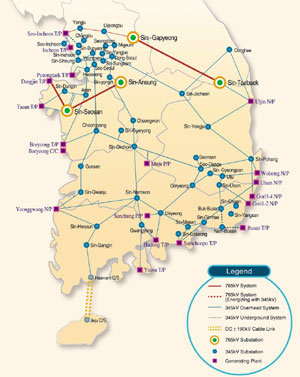
Construction of these two lines, which are routed mainly through mountainous country, commenced in February 1996 and completed in December 1998. The 689 tubular-steel towers support these transmission lines. The average height of these towers is 312 ft (95 m). The maximum tower height is 505 ft (154 m). The ratio of suspension to tension towers is 1.2. The height of each tower has been determined to maintain a mid-span electric field of 3.5 kV/m at 1 m above the ground level. The circuits had operated at 345 kV until the 765 kV gas-insulated substations are commissioned on May 2002. Now the circuits are in operation at the full 765 kV voltage through 765 kV operation of single circuit until May, 2003 as Figure. 1.
◇ Plan of 765 kV Interconnections in Future = The second & third phase includes the construction of 765 kV lines between Sin Gapyeong Substation in the north to Sin Gori Nuclear power Plant in the south via Seo Gyeongbuk and Sin Ansung Substation. The route totals to about 200 miles (320 km).
Ⅲ. Design of 765 kV Transmission Lines
◇ Conductor Selection = The selection of the conductor was just one of the features influenced by the need to minimize the electrical environmental impact on the population living in close proximity to these transmission lines. The designed audible noise (AN) level of 50 dB (A) for the 765 kV line in foul weather conditions was determined by the Korea Environmental Protection Act (KEPA).
This effectively excluded the large four-conductor bundle configuration from consideration. The audible noise characteristics of eight different conductor bundles were examined in a corona cage. The design of 345 kV lines uses two and four rail conductor bundles. Experience has shown that the six rail conductor bundles satisfy the KEPA criteria. The combination of the span length and tower height considerations for the 765 kV line resulted in the selection of the six cardinal conductor bundle, which has greater mechanical strength than the equivalent rail conductor bundle.
A full-scale test line of the 765 kV transmission line was erected in 1993 to evaluate the environmental impact of all the corona phenomena in the vicinity of the in-service six cardinal conductor bundles. The average AN level for the 36 month test period measured at 15 m from the outer phase was 48 dB (A) in foul weather and 42 dB (A) in fair weather. Table 4 shows the configuration and profiles of the cardinal conductors, spacing 40 cm, which is, based on 345 kV line design practices. The test line also afforded the opportunity to gain operational experience of the electrical and mechanical performance of the hardware and spacer-damper for the line prior to completion of the final specification.
Table 4. Standard of conductor
| Kinds of conductor | Stranded wire(cable) composition | Calculated sectional area (㎟) | Tensile strength (kg) | Outer diameter (mm) | Weight (kg/km) | Coefficient of elasticity | Coefficient of linear expansion (106/℃) |
| ACSR 480㎟(Cardinal) | Aℓ54/3.38 | Aℓ484.53 St 62.81 | 15,300 | 30.42 | 1,836 | 7,987 | 19.53 |
◇ Ground-wire Design = The shield angle of ground-wire should be under -8° or 1 meter outside of outer-most conductors. In case of OPGW(Optical Ground Wire), the allowable temperature and induction problem of communication cable due to induced current were considered. Sag was maintained under the 80 % of conductor sag to avoid the failure of contacting with the main conductors below.
◇ Above Ground Height Standard Design = Design value of height above ground for transmission lines is calculated considering the technical level of electric devices, field strength around the ground, height of trees under the lines, and crossing of other structures.
The minimum of conductor height was determined to maintain the maximum electric field below 3.5 kV/m at 1 m above ground in the flat urban areas and 7.0 kV/m in the mountainous areas. However, to protect the natural environment of the mountainous areas, it is not permitted to remove trees under the lines in Korea. So in reality, the electric field in these areas is less than the design value 7.0 kV/m. The minimum of conductor height for the 765 kV double circuit line is 28 m.
◇ Insulation Design = The towers of 765 kV double-circuit transmission lines are pretty tall. The selected shielding angle of 8 degrees in the ground wire location to the upper phase conductor gives perfect shielding irrespective of tower height and hillside effects. The designed isochronal level is 20, comparatively less than in most countries, and the outage rate due to lightning is estimated as 0.35 per 63 miles (100km) per annum assuming 10 to 15 ohm tower footing resistance.
The critical flashover voltage (CFO) of 1,580 kV in the switching pulse was assumed considering the maximum switching overvoltage of 1.9 p.u., atmospheric correction factor below 3,300 ft (1,000 m) altitude of 1.08, and a flashover to withstand voltage ratio of 1.176. At an instant ground fault of single-phase in each circuit the maximum switching overvoltage occurs, while the power frequency overvoltage of the sound phase in this fault situation is 1.2 p.u.
The minimum air clearance in the supporting tower was evaluated as 16.2 ft (4.95 m), the equivalent distance of 1,580 kV CFO in switching surge test in air insulator design. The number of insulator discs in a suspension string is 30 and the mechanical strength is 300 kN. For a tension string the comparable figures are 28 discs and 400 kN.
◇ Spacer-Damper and Fittings = A new type of spacer-damper was developed for the 765 kV transmission lines of Korea using an elastomer as the material to damp vibration amplitude. To improve the performance of the elastomer, the elastomer is ball-shaped to stabilize the physical characteristics from the effects of ozone, sunrays, low temperature, and other environmental factors. Eight elastomer balls per arm of the spacer-damper give the arm flexibility to damp three-dimensional vibrations. To overcome the problem of being loose in clamping bolts, the locking bolt and nut assembly has also been developed.
◇ Tower Design = According to the change of towers to the larger size, when angle steels are used, the double-member form is inevitable, and maintenance and repair are difficult. So, for main-member and diagonal-member, steel pipe member is adopted in which single-member application is possible. For arm-members, angle steels are used. To estimate the load of tower, Technical Standard for Electric Devices and tower design specification of KEPCO’ own are applied.
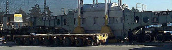
The tubular steel towers were constructed with components manufactured to maximum weight and length, and KEPCO used construction techniques different from former times. The Electrical-driven and remote-controlled climbing cranes with lifting capacity of 40 tons, working radius of 66 ft (20 m), and maximum working height of 500 ft (150 m) are used to reduce manpower requirements and the line construction period. These cranes assembled at the tower construction site are designed with low weight components (1.2 ton max) to facilitate transport to mountainous positions.
Helicopters are used to transport materials to sites where access is particularly difficult, but are not used to assist tower construction. The steel towers are hot-dipped galvanized during manufacture, but after erection the parts above 200 ft (60 m) are painted red and white in accordance with the aviation law. In the places having natural beauty, the towers are painted blue to minimize the visual impact.
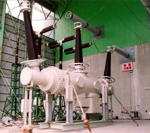
IV. Development of 765kV Transformers and 800kV GIS
◇ Design and development of 765 kV Transformers = Before construction 765 kV transmission, Korea utility company as well as associated companies had performed many preliminary rearches on optimal transmission conductors, main transformer, and circuit breakers for the localization of 765 kV equipments. In 1992, KEPCO had constructed 800 kV testing line to research optimal transmission conductor method and electrical phenomena of corona, sound, and electromagnetic field intensity around the testing line. Hyosung Corporation has first delivered three single-phase 3 MVA 765 kV transformers to the 800 kV testing line to energize the line. Hyosung Co. also has developed single-phase 500 MVA 765 kV Auto transformer as commercial type in 1996. However late in 1996, the capacity of 765kV auto transformer was finally changed to 666.7 MVA. Therefore, Hyosung Co. developed again single-phase 666.7 MVA 765 kV transformer and successfully finished and qualified the type test by KEPCO and KERI in 1999.
● Low Stresses on Tap Changer : The tap leads are brought out from near the neutral point of common winding instead of auto point. This enables to reduce the electrical stresses in tap lead and tap changer comparing when the tap leads are brought from auto point.
● Delivery : Total 15 units of 666.7 MVA 765 kV transformers have been delivered to KEPCO and Hyosung Co. received purchasing order of 6 units of single-phase 204 MVA GSU transformer. The GSU transformer is under design and delivered in March 2004.
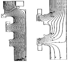
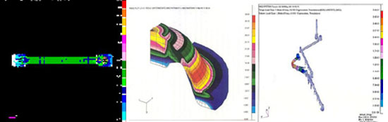
● Electric Field Analysis in GCB : The electric field analysis has been done to check preliminarily the dielectric capability of the designed GCB at the conditions of both closed and opened position by using commercialized program package, subsequently to reduce the design cost and increase the efficiency of development. The examples are shown in Fig. 3 (a) resulting from the electric field analysis between the bus and the earthed tank in the closed position of interrupter, and in Fig. 3 (b) resulting from the electric field analysis between poles in the opened position of interrupter. In particular, 3 dimensional electric field analysis has been conducted to estimate the dielectric withstand capability between poles of the interrupter with high accuracy, and the example of the results is shown in Fig. 4.
● Short-circuit current making and breaking tests performance of short-circuit tests = The principle specifications and test duties of the developed GIS are described in Table 9, and short-circuit tests (BTF, SLF, Capacitive current switching tests) was conducted by KERI. The synthetic method was used to test the specimen with the test-circuit having two separate sources for supplying the test voltage and the test current divided into two kinds, current injection method and voltage injection method according to the superimposed time of the voltage source.
Ⅴ. Conclusions
Through developing research using full scale 765 kV test line and other facilities in KEPRI Gochang Power Testing Center, KEPCO developed and has been operating double circuit 765 kV transmission lines successfully since 2003. The 765 kV transmission line of Korea is the first 765 kV class one in the world as the double-circuit AC transmission line. The lines were energized with 765 kV voltage, which is the highest transmission operation voltage in Asia, from May 2003. Design concept of the 765 kV transmission was focused on environmental aspects such as corona discharge, EMF, and wind noise etc.. 765 kV transformer and 800 kV GIS was designed using the several analysis methods, verified in type test in KERI and finally installed at several substation and power plant by Hyosung Co. After the commercial operation, the analysis and research on characteristics of double circuit 765 kV transmission and substation systems are being progressed to construct and operate the most optimal 765 kV transmission lines in the future.
Now a days Korea have been construting single circuit 765 kV transmission lines as the 2nd 765 kV project and other double circuit 765 kV transmission lines as the 3rd 765kV project. Also Korea has been exporting the 765 kV technology to foreign country’s 765 kV project.
Study on Aging of 765kV Polymer Insulator at KEPRI’s Gochang Test Facility
EPRI and KEPRI are conducting a joint study on 765kV polymer insulator aging (project ID No. 064253). A long term (3 years) aging test at Gochang Test Site has been constructed and implemented by KEPRI.
Although industry experience exists at 765kV polymer insulators exist, this experience has been obtained in low contamination conditions. The Gochang test site provides the unique capability of evaluating insulators in a contaminated environment. By doing so the industry will be provided much needed and valuable information on the performance on polymer insulators applied at Ultra High Voltages (UHV) in contaminated conditions.
In February 2007 EPRI Researchers visited the Gochang test site and discussed the test in detail. The number and location of test samples, approach to installation, parameters to be monitored, inspection schedule and exchange of dimensions were discussed among numerous other topics.
This document is intended to layout the test plan and approach in detail. This will be a reference document for both EPRI and KEPRI researchers as well to inform the other collaborative participants.
The test has the following objectives:
● To determine the performance of 765kV polymer insulators in a contaminated environment.
● To identify any significant issues related life expectancy of 765kV polymer insulators in a contaminated environment.
● To increase understanding of aging mechanisms of polymer insulators installed at UHV voltages in contaminated environments.
● To determine whether there is a difference in the performance of different designs and dimensions of polymer insulators at UHV voltages in contaminated conditions.
● Comparison of performance against porcelain, glass and RTV(Room Temperature vulcanizing) silicone rubber coated insulator strings.
● To facilitate worldwide collaboration between utilities that are implementing 765kV technologies.